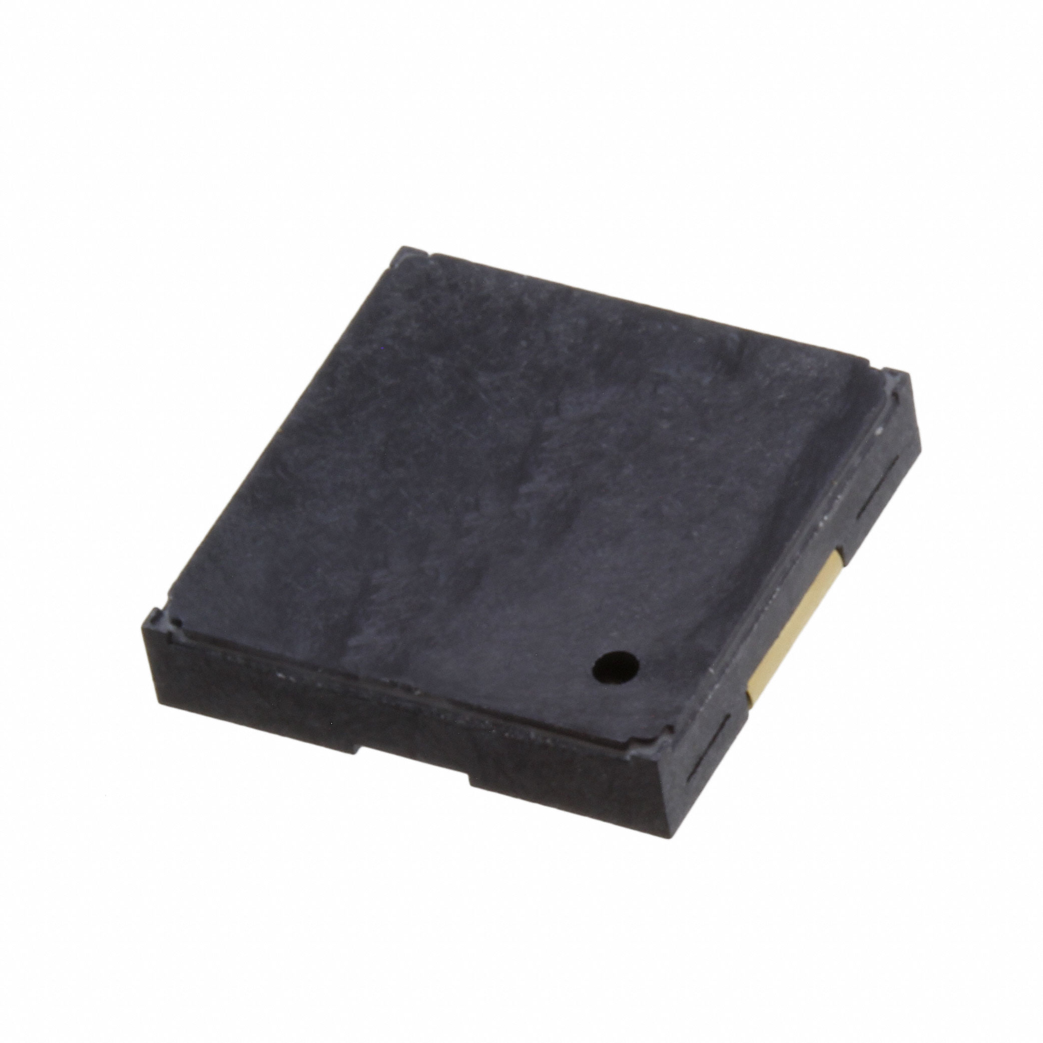
Mfr Part # 5345
ESP32-S2 REVERSE TFT FEATHER
Adafruit Industries LLC
License: See Original Project 3D Printing Wifi ESP32
Recently, my friend got a new dog, and he's been having a hard time remembering whether or not he feeds the dog throughout the day. Because he's a maker, he wanted to design and build a device that would help remind him whether or not he feeds his dog.
The thing I like about this project is that it doesn't have to be specific to feeding your dog. This little device could help you remember to do anything three times a day. Whether that's watering your plants, getting up to stretch, taking a walk, or maybe taking medication. This could be customized to fit any need.
He got started on this project and has a really solid foundation, but he asked for my help, so I stepped in to help him build this project.
These are his design requirements:
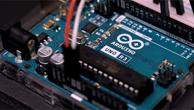
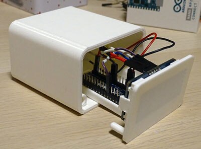
I'll use a Wi-Fi-enabled microcontroller and connect it to the Telegram messaging app. Any time the light turns red, meaning that it's been too long, and the dog has not been fed, it will send him a Telegram message. I need to design a minimal and nice-looking case for this that everything will fit into, and it will sit on their kitchen counter and not look too distracting. As I'm thinking about this design off the top of my head, I'm kind of worried about how much wiring there's going to be. I think I'll design a circuit board that everything will connect to, and it will take care of the rat's nest of wires that I want to avoid. I'll start by drawing this circuit on a computer and designing the PCB. The first thing I need to do is add the microcontroller. I will use the ESP32 feather board from Adafruit. I find the symbol for that and add it to the schematic.
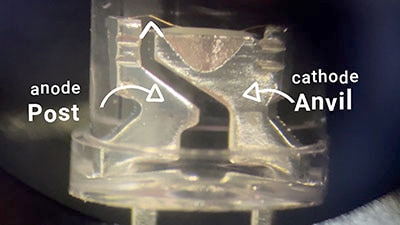
Next, I need to create a symbol for that LED push button. It doesn’t exist in the library, so I'll have to make it from scratch. I'll take an existing push button that has an LED in it and just modify that symbol to have a red, green, and blue LED. These RGB LEDs are common cathode. I can tie each LED cathode to ground and the anode to one of the pins on the push button. I add a current-limiting resistor to each of the LEDs and then I give them a net name that I can tie to the microcontroller.
On the microcontroller side, I just need to assign each of these net names open so that I can control them individually. Finally, I asked my friend if he wanted this to make any sounds. He said, “Absolutely not!” (He doesn't want it to be annoying, but I think I'm going to sneak a little buzzer in here just in case at some point, he decides he wants to add a little bit of sound to this project.) One of the nice things about designing a PCB is that it doesn't cost extra to add footprints. When I go to build this board, I don't have to place that buzzer component on there. I can just leave the footprint blank. That's pretty much it for the schematic. I can assign footprints to all of these symbols and then design the board layout.
I lay all three buttons in a horizontal configuration, and I quickly decided that I didn't like that design and that a vertical orientation would look a lot better. So instead, I'll place the footprints for my buttons in a vertical layout, and then I add the current limiting resistors to each of those LEDs, and then finally I connect the microcontroller pins to their proper inputs and outputs.
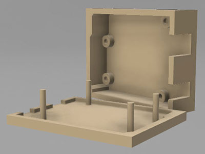
Before I can design the board outline, I need to know what my mechanical enclosure is going to look like. I open up Fusion 360 and start modeling the enclosure with a simple box. Next, I use the fillet tool to give it some rounded edges. I know that we want the enclosure to sit at an angle, so I use the chamfer tool to create a 45-degree angle on the bottom. Once I have those features, I use the shell tool to hollow out the box so that I can fit all the stuff inside of it.
The enclosure with all of the electronics will be 3D printed while the base plate and the faceplate will be cut out of metal. My friend and I discussed different ways to make sure this little device doesn't slide around. We came up with the idea of just using a heavy metal plate as the base. I ordered them from an online service, and hopefully, the weight of the plate will be enough to keep this thing from sliding around on the counter. I add some holes into the design so that I can screw these pieces together.
Next comes the faceplate. I use the same spacing that I used on the circuit board design to create three holes for the faceplate, and that's where the buttons will be inserted. I fiddled with this for a couple of hours, adding some minor details here and there and adjusting a few things, and I'm pretty happy with how it looks.
At this point, I'm ready to order my PCB, the laser-cut parts, and electronic components and print the 3D-printed parts here in my workshop.
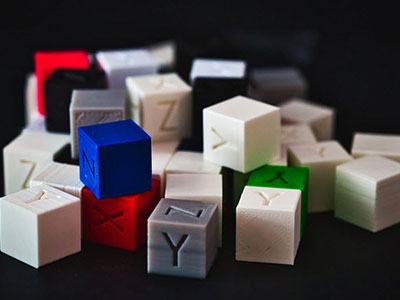
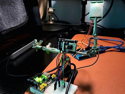
I used a carbon fiber filament, and this thing turned out perfect. Look how flawless that looks! While I wait for the circuit board and the laser cut parts to arrive, I 3D print some mock-up pieces out of plastic, and I’ll use those to assemble this and do a dry run.
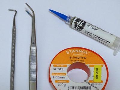
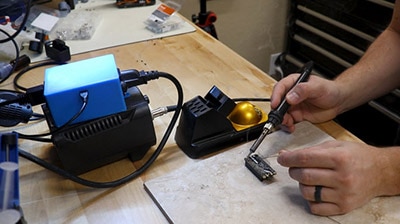
There’s a big downside to this design; these buttons have to be soldered to a PCB, but before I can do that, they have to slide through the faceplate. Once I slide these buttons through the faceplate and solder them onto the PCB, this becomes a permanent subassembly. There's no way to remove them from the faceplate without desoldering them from the PCB. I knew that going into it, but that's a tradeoff that I'm willing to make.
All the parts that I ordered arrived, and I'm excited to start assembling this. I’m also excited to try something new for the front face panel. I ordered some aluminum composite material; as the name suggests, it's a composite material. The center of it is a high-density plastic, and the outer two skins are made from a thin sheet of aluminum. The reason I chose black aluminum composite material is because I want to laser engrave a logo as well, as some labels on this face plate.
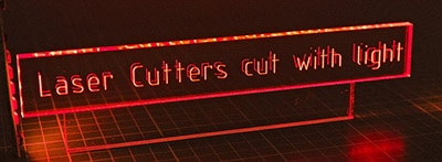
To engrave this faceplate, I use a CO2 laser cutter. This laser cutter has a built-in camera to help align things, but if I want to get the text to align perfectly with these holes, I'm going to have to use a little bit of a trick. The first thing I do is put a piece of cardboard into the laser cutter. Then, I open up my design in the laser software and I make sure I add an outline just a little bit bigger than the outline of the faceplate. I’ll put that outline on a separate layer and cut it out of the cardboard just on its own. Now, I can place the faceplate inside that cutout, and all of the other engraving that takes place on the other layers will line up perfectly.
My friend with the dog came up with the name “Chow Check” for this product, and he even designed a little logo that I'm laser engraving on the faceplate. This engraving is way better than I expected so I will definitely use this process in the future.
As I said earlier, I have to install the buttons through the faceplate and then solder them to the PCB, and this becomes a permanent subassembly. I have to do this step now before it is too late. If I assemble everything first and then try to engrave it, it won't work. This is one of those things that I'm spending a little extra time on to make sure I get correct because if I do this wrong, this part is basically scrapped, and I have to start over again.
Do you remember earlier when I talked about one of the requirements being that this thing doesn't slide around too much? My solution to that was to build a really heavy baseplate. I chose a quarter-inch steel plate as the material, but I wonder how much more the baseplate weighs than the enclosure and the electronics. I put the enclosure and the electronics on a scale, and it looks like they weigh about 86 grams (3 oz.). If I put the baseplate on there, I see that it weighs 164 grams (5.8 oz). That's roughly twice as much! When I attach the baseplate to the bottom of the enclosure, that weight should be more than enough to keep it from sliding around too much.
With all of these components under the board, I'm ready to program this project. I have the Arduino IDE open, and I start by defining which GPIO pins I need. Each button has a switch as well as a red, green, and blue LED pin. I can always refer back to the schematic to remember which pins I assigned to each. Next, I use the pinMode() function to set the switches as inputs and the LED pins as outputs. In the main loop, I pretty much have two tasks… 1) I want to structure this in a way where I assign the colors to each of the buttons, and 2) I use a custom function to actually set the colors on the buttons. I make sure not to use any delays in the main function because I want to continuously assign and set these LEDs. I need to write some conditions to set the color either to red or to blue, so I write an “if statement” and check to see if the current time is greater than the task time plus my 15-minute grace period. If that condition is met, then I assign the color red. Otherwise, the code checks to see if the current time is later than the task time, and if so, I'll set the color as blue. It's always good to have a default condition. If no other conditions are met, I'll assign the color black, which just means that the LEDs will be turned off. Of course, I'll do this for all three buttons.
When the current time reaches midnight, I want everything to reset and turn the LEDs off. To read the button presses, I use an interrupt service routine, as I do with all electromechanical switches. I take care of bouncing within that interrupt service routine by checking to see if it's been long enough for the bouncing to have stopped. If so, I set the color to green.
One nice thing about using a Wi-Fi microcontroller is that I can get the current time using an NTP (Network Time Protocol) server, and I want to make sure that I'm updating that as often as I can in the main loop.
A lot of this is pseudocode, and it's not fully fleshed out, but this is the general idea of how this code works. To begin, all three buttons are turned off. After a few moments, the light will turn blue because it will be time to feed Luna breakfast. Now, if my friend Jonathan is passing by and he happens to see that the light has turned blue, he can go feed the dog and push the button, and the button will turn green, indicating that the dog has been fed. Let's say one of his kids comes by and pushes the button without actually feeding the dog; each button can be reset to their previous state by holding it down for 3 seconds. But what happens if Jonathan doesn't walk past and see that it's time to feed the dog? After 15 minutes, the light will turn red, and Jonathan will get a telegram message sent to him, reminding him to feed Luna lunch. Then, if he feeds the dog, he presses the button, and it still turns green.
However, the telegram interface doesn't stop there. If I want to change any of the settings for the buttons, all I do is type in /settings, and a little menu pops up. I can choose which of the three tasks I want to edit. For example, let's say I want to edit the lunchtime. Instead of feeding Luna at 1:00 p.m., let's say I want to feed her at 1:30 p.m. All I have to do is reply to the message and type in “13:30” (24-hour time), and it replies, letting me know that the time has been changed. Remember earlier how I held down the button to reset it back to its previous state? I can do the same things right here in the app. I can choose “reset feed Luna lunch” and the LED will change from green back to its previous state.
What I like about this project is that it doesn't have to be used to remind you to feed a dog. It can be used to remind you to do other tasks. I'm still working on the code, but the next feature I want to add is being able to edit the task label, so instead of saying “Feed Luna,” it can say, “Go outside and take a walk.”
If you're interested in building a task reminder like this, all of the source files will be available on my GitHub.