Controlling Stepper Motor 28byj-48 With IR Remote Using Arduino
2026-05-15 | By Ron Cutts
License: GNU Lesser General Public License Bluetooth / BLE Microcontrollers Motors Stepper Arduino ESP32
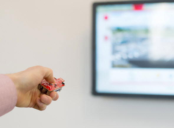
In this tutorial, we are going to learn how to control a stepper motor using an IR remote and Arduino.
If you press & hold the left or right button on the remote, the motor will spin as long as you hold the button on the remote. If you press the down or up button once, the motor will start to continuously spin left or right.
Watch the video!
Learn more about Visuino: What is Visuino
What You Will Need
Arduino UNO (or any other Arduino or ESP32)
Visuino program: Download Visuino


The Circuit
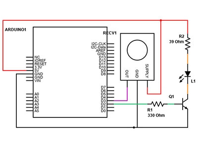
Connect the IR RECEIVER pin (S) to Arduino Digital pin[2]
Connect IR RECEIVER pin [+] to Arduino positive pin[5V]
Connect IR RECEIVER pin [-] to Arduino negative pin[GND]
Connect the Stepper Motor to the Stepper Motor Driver
Connect Arduino pin [5V] to the driver board pin [VCC]
Connect Arduino pin [GND] to Driver Board pin [GND]
Connect Arduino digital pin [8] to Driver Board pin [IN1]
Connect Arduino digital pin [9] to Driver Board pin [IN2]
Connect Arduino digital pin [11] to Driver Board pin [IN3]
Connect Arduino digital pin [12] to Driver Board pin [IN4]

Start Visuino, and Select the Arduino UNO Board Type
Start Visuino as shown in the first picture. Click on the "Tools" button on the Arduino component (Picture 1) in Visuino. When the dialog appears, select "Arduino UNO" as shown in Picture 2


In Visuino, Add Components
Add "Infrared Remote Receiver" component
Add 3X "Digital Multi Source" component
Add 3X "Digital Multi-Source Merger" component
Add "Digital (Boolean) Value" component
Add "Toggle(T) Flip-Flop" component
Add "4 Wire Stepper Motor" component


In Visuino Set Components
Let's set the commands for the left & right and up & down buttons on the remote. You will need a code for that. In my case, it was 16734885 & 16716015 and 16718055 & 16730805. Each remote might use a different code. If you do not have it, check out the next step on how to obtain the code.
Double-click on "InfraredReceiver1," and in the "Elements" window, drag "Decode NEC Command" to the left side, and in the properties, set Value to 16716015
Drag another "Decode NEC Command" to the left side, and in the properties, set Value to 16734885
Drag another "Decode NEC Command" to the left side, and in the properties, set the value to 16718055
Drag another "Decode NEC Command" to the left side, and in the properties, set the value to 16730805
Close the "Elements" window
Double-click on "DigitalValue1" and in the "Elements" window, drag "Set Value" to the left side, and in the properties, set Value to False
Drag another "Set Value" to the Left side, and in the properties, set Value to True
Close the "Elements" window
Select "Stepper1" and in the properties, set "Half Step" to False
Select "Stepper1" and in the properties, set "Steps Per Second" to 500
Select "Stepper1" and in the properties select "Enabled" and click on the Pin Icon and select "Boolean SinkPin"
Select "Stepper1" and in the properties select "Reversed" and click on the Pin Icon and select "Boolean SinkPin"


How to Obtain the Codes From a Remote Controller
Connect "InfraredReceiver1" pin [Out] to Arduino Serial pin [0]
Upload the Arduino Code & open Serial tab, Select Port & click Connect Button
Click on the Left & Right, Up & Down buttons on the remote, and you should see the codes.

In Visuino Connect Components
Connect Arduino Digital pin [2] to "InfraredReceiver1" pin [Sensor]
Connect "InfraredReceiver1" > "Decode NEC Command1" pin [Out] to "DigitalMultiMerger1" pin [0]
Connect "InfraredReceiver1" > "Decode NEC Command2" pin [Out] to "DigitalMultiSource1" pin [In]
Connect "InfraredReceiver1" > "Decode NEC Command3" pin [Out] to "DigitalMultiSource2" pin [In]
Connect "InfraredReceiver1" > "Decode NEC Command4" pin [Out] to "DigitalMultiSource3" pin [In]
Connect "DigitalMultiSource1" pin [0] to "DigitalMultiMerger1" pin [1]
Connect "DigitalMultiSource1" pin [1] to "DigitalMultiMerger3" pin [0]
Connect "DigitalMultiSource2" pin [0] to "TFlipFlop1" pin [Clock]
Connect "DigitalMultiSource2" pin [1] to "DigitalValue1" > "Set Value1" pin [In]
Connect "DigitalMultiSource3" pin [0] to "TFlipFlop1" pin [Clock]
Connect "DigitalMultiSource3" pin [1] to "DigitalValue1" > "Set Value2" pin [In]
Connect "DigitalValue1" pin [Out] to "DigitalMultiMerger3" pin [1]
Connect "DigitalMultiMerger1" pin [Out] to "DigitalMultiMerger2" pin[0]
Connect "TFlipFlop1" pin [Out] to "DigitalMultiMerger2" pin[1]
Connect "DigitalMultiMerger2" pin [Out] to "Stepper1" pin[Enabled]
Connect "DigitalMultiMerger3" pin [Out] to "Stepper1" pin[Reversed]
Connect "Stepper1" pin [0] to Arduino digital pin [8]
Connect "Stepper1" pin [1] to Arduino digital pin [9]
Connect "Stepper1" pin [2] to Arduino digital pin [11]
Connect "Stepper1" pin [3] to Arduino digital pin [12]


Generate, Compile, and Upload the Arduino Code
In Visuino, at the bottom, click on the "Build" tab, make sure the correct port is selected, then click on the "Compile/Build and Upload" button.

Play
If you power the Arduino module and press a Left or Right button on the IR remote and hold it, the motor will turn right or left, and if you press the up or down button on the IR remote, the motor will start spinning right or left each time.
Congratulations! You have completed your project with Visuino. Also attached is the Visuino project that I created for this tutorial. You can download it and open it in Visuino: https://www.visuino.eu