Designers Need to Understand the Cause and Impact of VCR and How to Mitigate It
Contributed By DigiKey's North American Editors
2025-10-29
Many designers are unaware that resistors have a voltage coefficient of resistance (VCR) as well as a temperature coefficient of resistance (TCR). That is understandable because in low-voltage and low-resistance applications, the voltage effects are minor and well masked by the temperature effects. However, in circuits that use high resistances and/or high voltages (HVs), resistance variability with voltage can be a big concern. These circuits are used in applications such as HV power supplies, transimpedance amplifiers (TIAs), HV LED lighting, and pulsed communications systems. Designers of such circuits need to understand the cause and impact of VCR and how to mitigate it.
This article provides an overview of VCR and its impact on circuit designs. It then uses examples of low-VCR resistors from Stackpole to illustrate how to select and apply such devices to minimize the effects of VCR in support of accurate and reliable operation of critical circuits.
What is VCR?
The VCR of a resistor can be defined as the change in resistance value proportional to an applied voltage. It is generally measured in units of parts per million per volt (ppm/V) and can be calculated using the equation:

Where:
R₁ is the resistance value, in ohms (Ω), at a reference voltage (V₁)
R₂ is the resistance value, in Ω, at the test voltage (V₂)
V₁ is the reference voltage
V₂ is the test voltage
The VCR can be positive or negative. A positive VCR indicates that the resistance will increase with increasing voltage across the resistor, while a negative VCR indicates that the resistance will decrease.
Typical HV chip resistors with a VCR of 200 ppm/V to 300 ppm/V will show a 20% to 30% change in resistance for a change in applied voltage of 1,000 V. Choosing a resistor with a VCR of 25 ppm/V to 50 ppm/V reduces the change in resistance to 2.5 to 5% for the same 1,000 V change.
The standard testing method for measuring VCR follows MIL-STD-202G Method 309. This standard establishes uniform methods for testing electronic components, specifying the standard test voltage equal to the maximum specified working voltage, and the reference voltage level of 10% of the maximum working voltage.
How to minimize VCR
VCR can be minimized by appropriate design and material selection. There is an engineering tradeoff required in the choice of resistive materials here because low-VCR resistive materials can improve VCR but can also increase TCR, reducing temperature stability. The selection of lower resistance inks will also improve VCR but limit the maximum resistance achievable. Careful selection of the type of resistive ink and the application method can optimize VCR.
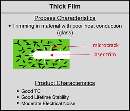
Laser trimming can also have an impact on VCR. Untrimmed resistors typically yield resistance values within 5 to 20% of the intended value. Laser trimming is used to adjust resistance values to within a smaller tolerance, for instance, within 1%. The laser trimming process can degrade VCR by generating microcracks that result in local, unintended impedance changes, which increase VCR (Figure 1).
 Figure 1: The physical effects of laser trimming thick-film chip resistors can degrade VCR. (Image source: Stackpole Electronics Inc.)
Minimizing the use of laser trimming reduces these effects, as does the selection of the laser trimming geometry and the size of the package. In general, larger packages offer reduced VCR.
Applications for low-VCR resistors
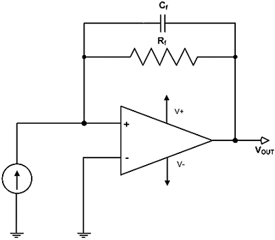
Low-VCR chip resistors find applications in LED lighting, medical devices, audio-visual equipment, and communications systems that require HVs and/or high resistance values. A good circuit example is a TIA (Figure 2). This amplifier takes a current input and outputs a proportional voltage.
 Figure 2: A TIA converts a current input into a voltage output proportional to the feedback resistor value. (Image source: Art Pini)
The output voltage of a TIA is equal to the product of the input current and the feedback resistor, Rf.
A common usage of the TIA is to interface with photodiodes, accelerometers, photomultiplier tubes, and similar sensors where the sensor current response is more linear than its voltage response. Generally, these applications require high gain, which in turn means a high-value feedback resistor. Since the input end of the resistor is held at ground, the resistor sees the full output swing. In a great many cases, the input signal may be pulsed, as in electromagnetic interference (EMI) or mechanical shock testing, resulting in large voltage swings across the resistor.
A change in the resistor value related to the voltage across the resistor will result in the amplifier gain being modulated. This modulation adds a squared term to the voltage output. The squared term increases the second and other even harmonic terms in the output, causing linearity and harmonic distortion issues. The amount of resistance variation does not have to be great to produce significant distortion levels.
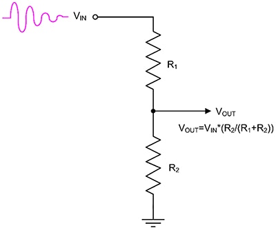
Another application where low-VCR resistors are used is in voltage dividers (Figure 3), which are used to reduce a voltage level.
 Figure 3: Low-VCR resistors are used in voltage divider circuits; these reduce the voltage level of a signal and are typically used for feeding back a high voltage to a device with a lower voltage-input rating. (Image source: Art Pini)
The voltage divider is used for applications such as sensing the output of an HV power supply and feeding that back to the power controller. It might also be used as an attenuator to reduce an HV signal, such as an EMI pulse or a lightning strike, to a safe level for a measuring instrument.
In almost all applications, the upper resistor, R1, has a much higher value than that of the lower resistor, R2, and has the higher voltage across it. A low-VCR resistor is required for applications where the input signal varies, as in measuring an EMI pulse. The VCR causes the divider output attenuation to vary with the input voltage level, causing an error in the attenuation.
Assuming the input is a 1,000 V peak damped sine EMI pulse, if R2 is 1000 Ω, R1 is 1 megaohm (MΩ), and they are ideal resistors, the output is a damped sine with a peak amplitude of 0.999 V. If, however, R1 has a VCR of -200 ppm/V, then with an input voltage of 1,000 V, the resistance will decrease by 200 kilohms (kΩ). The attenuation of the voltage divider will be reduced, and the peak amplitude of the output will be 1.25 V. As the input voltage varies, the varying attenuation will distort the output waveform.
When dealing with high resistor values and HVs, it is essential to consider the VCR.
Examples of HV, low-VCR chip resistors
The Stackpole RVCU series of HV, low-VCR chip resistors provides exceptional voltage stability over voltage ranges of 800 V to 3,000 V, depending on the package size. The series offers resistors with resistance tolerances of 0.5% to 5% over a range of 75 kΩ to 30 MΩ. They all have a VCR of ±25 ppm/V for resistor values below 3 MΩ and 50 ppm/V for values greater than 3 MΩ to 30 MΩ. The TCR is common across all packages at 100 ppm/°C. They are AEC-Q200 compliant for automotive applications, as well as anti-sulfur ASTM-B-809 tested.
The RVCU family contains resistors in 1206 (3216 metric), 2010 (5025 metric), and 2512 (6332 metric) surface-mount packages (Figure 4).
 Figure 4: Shown are the mechanical dimension callouts of the RVCU series of surface-mount chip resistors. (Image source: Stackpole Electronics Inc.)
The package model number encodes the length and width dimensions. The first two numbers represent the package length, the last two represent the width. The US dimensions are in hundredths of an inch (in.), to the nearest integer value. The metric dimensions are tenths of a millimeter (mm). All three packages have a standard height of 0.022 in. (0.55 mm). The maximum working voltage specification varies with the package size.
The Stackpole RVCU1206FT1M00, for example, is a 0.33 watt, 1 MΩ, 1% thick-film resistor in a 1206 surface-mount package. It has a maximum working voltage rating of 800 V with a maximum overload voltage limit of 1,000 V.
For slightly higher power levels, the RVCU2010FT1M00 is a 0.5 W, 1 MΩ thick-film resistor in a 2010 surface-mount package. This resistor has a tolerance of 1%, a maximum working voltage of 2,000 V, and a maximum overload rating of 3,000 V.
The Stackpole RVCU2512FT1M00 is a 1 MΩ, ±1% thick-film chip resistor with a power rating of 1 W.
It comes in a 2512 surface-mount package. The working voltage of this device is higher than the RVCU2010FT1M00 at 3,000 V, with an overload-voltage rating of 4,000 V.
Conclusion
HV and high-resistance circuits need resistors with a low VCR for accuracy and stability. The Stackpole RVCU series chip resistors provide a low VCR of 25 ppm/V to 50 ppm/V and are designed to offer exceptional stability at voltages from 800 V to 3000 V.

Disclaimer: The opinions, beliefs, and viewpoints expressed by the various authors and/or forum participants on this website do not necessarily reflect the opinions, beliefs, and viewpoints of DigiKey or official policies of DigiKey.


